I have taken video instructions for the new drain valve but until this is edited and published, here is the low down:
The Drain Control Valve should be installed on the main (centermost) drain, as this is the one that will handle the majority of the flow.
The purpose of the valve is to restrict flow just enough to allow the drain to convert to a full siphon and purge out the air. This concept is referred to as a “tuned siphon”. If you leave the valve all the way open, you will 1) not get as much flow through the drain as you would if the valve was closed, 2) you will get excess flow through the secondary drain, and 3) it will be noisy (sucking air) and you will get a lot of bubbles. Start with the water running and valve open (screw out all the way) and then turn it until the unit goes silent. That’s it!
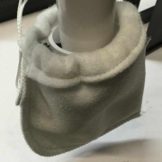
The purpose of the drawstring bag is not to filter, it is to prevent bubbles from going everywhere, especially for the first few weeks. The top of the bag (and coupler) can be underwater. This will force the bubbles to rise to the surface while not trapping life such as copepods.
You may be able to remove the filter bag after the screen matures. I do not run filter bags on any of my mature scrubbers – with a mature screen and a tuned drain, you will have little to zero bubble issues.
The flapper is opened and closed by turning the thumbscrew. This replaces the bulky ball valve or a gate valve. It’s very simple. The valve should be at the low end of the run of drain plumbing, it is installed in one of the 1.5″ pipes such that you can cut the top part of the pipe to length so that the bottom of the valve-end of the pipe is about 0.5 to 1″ below the water surface (sump operating water level under the scrubber) but you can place it lower under the water: I would not recommend more than 2″ below, otherwise air may not easily/quickly purge from the drain.
Once that is cut to the correct length, slide the 2″ coupler with thumbscrews over the submerged end of the pipe and tighten it down. The top of the coupler can be (and actually is recommended to be) fully submerged.
Next, slide the drawstring filter bag over the coupler (over the thumbscrews) and tighten down so that it doesn’t slip off – it doesn’t have to be cinched way down tight, just enough to keep it in place.
Put all the pieces together (if you didn’t install them in place) and you are ready to fire up the scrubber and tune the drain!
https://www.turbosaquatics.com/wp-content/uploads/2019/12/blog-valve.png400400budhttps://turbosaquatics.com/wp/wp-content/uploads/2019/12/Turbos-Aq-2-Color-Logo-spread-300x118.pngbud2019-12-10 00:15:382020-12-15 07:40:03Drain Control Valve (inline flapper valve)
The Rev 4 L2 comes with 2 fixtures that must be inter-connected: One fixture is the Master and the other is the Slave. The connectors are foolproof so you cannot connect these incorrectly.
The correct orientation of the fixtures is with the cords coming out of the bottom of the fixtures. The LED boards are offset to line up with the center of the screen.
The fixtures come pre-installed for shipping with the interconnect cables coming out of opposite ends of the scrubber and then connected together inside the growth chamber: you will need to remove one fixture and reverse the direction of the cord so that both cords come out of one side of the scrubber so that they may be connected together around one end of the scrubber body. To do this, simply bend or rotate the cords (the cable is a sheath with 4 #20 solid copper wires inside).
You can also exchange the location of each fixture to your preference. The interconnect cables (4-pin connectors) can be routed around either end of the scrubber. I recommend that you remove both fixtures and decide which way you are going to set them up so that you can easily maintain the scrubber, and once the main body of the scrubber is installed where you want it, install the fixtures and connect them. From that point forward, you should not need to remove the fixtures unless you need to remove the entire scrubber.
Similarly, you should choose where the power supply wires will be routed (this is the 2-pin female connector on the Master fixture). This also may be routed in either direction. Connect the power supply cable to the power supply and plug in the power supply.
I recommend routing the interconnect cables around the opposite end that you plan to use for removal of the Growth Chamber, but this is not critical.
The Rev 4 L4 comes with 2 fixtures and 2 power supplies. There are not interconnect cables (this is done internally within each fixture set). You can choose which direction to route the power supply cables. Connect the power supply cable to the power supply and plug in the power supply.
Note: When disconnecting and reconnecting the power supply to the fixtures, you need to allow the power supply to de-energize in order to avoid “zapping” the LED Driver and/or LED boards. Failure to de-energize the power supply when connecting or disconnecting the light fixtures can result in short series or momentary power surges to the LED boards, and this can result in failure of LEDs (both individually and in total). I’ve got burnt out board to prove it, so just trust me on this one.
When disconnecting, first unplug the power supply, wait about 5-10 seconds, and then disconnect the fixtures from the power supply.
When reconnecting, first connect the fixtures to the power supply and then plug the power supply into the wall.
If you inadvertently connect the power supply to the wall first (even for only a fraction of a second) you must unplug the power supply and wait at least 30 seconds for it to de-energize before connecting the power supply to the LED fixtures.
Setting the LED intensity level
The potentiometers on the driver board (called SMD, or Surface Mounted Device, potentiometers) are pre-configured with the reds at 100% and violets at 50%. Unless you are going to connect the custom LED driver to a PWM controller, I do not recommend changing the set points of these potentiometers.
On the Master fixture there is an external dimming knob (potentiometer) in a 3D printed enclosure. This will dim all the LEDs in unison, in proportion to the setting of the SMD potentiometer. So with the default setting, if you turn the external knob to 50%, the reds will be at 50% and violets at 25%. The dimming knob should be set at 50% or less initially. This can stay at that level for quite a long time, for some, indefinitely.
An important note: the external dimming knob is a special type called an Audio Taper Potentiometer, which allows for very linear dimming operation, but it works OPPOSITE of what you would expect. Turn all the way left (counterclockwise) to obtain maximum intensity (the “12 o’clock” position), turn the knob all the way right (clockwise) to obtain minimum intensity (about 10% at the “11 o’clock” position). The knob is removable, but is shipped such that the 12 o-clock position is 100%. With this reference point, 10% is at about the 11 o-clock position, so 50% should be near the 5 o-clock position.
Operational settings
As for the number of hours/day to run the LEDs, in the past, my recommendation has been 9 hours/day max at first. However, with the dimming knob function, you may be able to further reduce the intensity to a level where you can run for longer hours (18, 20, 22, or more) without causing “photosaturation” – which is when you have no algae growth, and way too much light. I recommend that you write down your intensity and duration settings and then note the resulting growth a few times a week, and take pics if you want and send them to me or post them on your favorite forum (and link me to the thread if I don’t reply!)
I would recommend initially setting the dimming knob in about the 6 or possible 7 o’clock position, and running the LEDs for 12 to 14 hours/day for the first week. For the second week, 6 o’clock position, 14 hours/day. By that time, you should need to do your first cleaning, which is just a swipe of your palm across the screen, and a very light rinse with slow running, room temperature tap water (or, just pour a cup of tank water over the screen after the palm-swipe). Then, continue with the 6 o’clock / 14 hrs/day for another week. Depending on growth, you may be able to increase intensity a bit, but take it one step at a time. Don’t go to 100% after the 2nd week!
https://www.turbosaquatics.com/wp-content/uploads/2019/12/blog-led-1.png400400budhttps://turbosaquatics.com/wp/wp-content/uploads/2019/12/Turbos-Aq-2-Color-Logo-spread-300x118.pngbud2019-12-10 00:14:432020-12-15 07:40:05LED Fixture operation and settings
Most aquarists are familiar with solvent welding (bonding) PVC fittings & pipe together. But when it comes to bonding PVC to ABS, there are a few differences that are very important.
With respect to the most recent Turbo Algae Scrubber, these differences are very important – improper solvent welding can lead to weak and leaky joints, which may require part replacement in order to remedy.
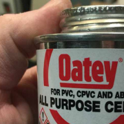
Rule #1: All Purpose Cement is ideal
One that lists both ABS and PVC on the label. In reality, most any cement is going to be fine, like Oatey Medium Clear. Just make sure to follow Rule #2.
I used to recommend trying to use Transition Cement, but this is not really necessary. What is more important is not applying primer OR cement/solvent to the ABS part – ONLY the PVC side. This is covered in Rule #2
Likely, regular PVC cement will work also, but I have not thoroughly tested this. People regularly bond PVC pipe into ABS bulkheads using standard PVC cement, so it’s probably not the worst thing you can use (however, let it cure overnight if in doubt!!)
Transition Cement can be found at just about any hardware store. It is light green in color, and opaque. It typically comes in a can with a green label.
Rule #2: Do not use primer on the ABS part
This is the most important rule! Primer is not required, but it is also not recommended. Use primer only on the PVC part. If you want, you may wipe the ABS part clean with a damp rag or another non-solvent cleaner.
Rule #3: Apply cement to the PVC part
Do not apply the cement liberally, as this can cause pooling; this generally doesn’t weaken the joint significantly, but it makes for quite the mess.
Do not apply cement to the ABS side of the joint.
If you think you need to practice, use 2 PVC fittings that you can throw away afterward. It’s a lot cheaper to do that than to mess up the scrubber parts.
Rule #4: Do not twist fittings back and forth when pushing together
If you twist the fittings back and forth as you push the parts together, this can cause voids and channels to form in the joint that can result in leaks.
This is actually a general rule for solvent welding plastic fittings that some are unaware of. When pushing the parts together, turn the fitting only 1/4 rotation in a single direction as you push the parts together, then hold the 2 parts still for 15-30 seconds and allow the solvent to set up.
Special note:
The Slot Pipe is not reversible – it can only be oriented in the Growth Chamber in one direction, so you must determine which end the cap should be bonded to according to the way you plan to set up and operate the scrubber!
https://www.turbosaquatics.com/wp-content/uploads/2019/12/blog-pvc.png400400budhttps://turbosaquatics.com/wp/wp-content/uploads/2019/12/Turbos-Aq-2-Color-Logo-spread-300x118.pngbud2019-12-10 00:13:192020-12-15 07:40:09Bonding PVC Pipe to the ABS Parts
This article contains the critical information you need to know when setting up your Turbo Algae Scrubber in a short format, with links to the more in-depth articles that are specific to the individual items/steps.
All Purpose Cement is ideal – one that lists both ABS and PVC on the label. In reality, most any cement is going to be fine, like Oatey Medium Clear. Just make sure to click the link above and follow Rule #2
I used to recommend trying to use Transition Cement, but this is not really necessary. What is more important is not applying primer OR cement/solvent to the ABS part – ONLY the PVC side. This is covered in Rule #2
Do not apply primer OR solvent/cement to the ABS.
Do not twist fittings back and forth when pushing together – turn the fitting only 1/4 rotation in a single direction as you push the parts together.
Slot pipe is not reversible, choose orientation before bonding PVC adapters.
Do not inter-connect fixture underneath the scrubber (connector is not submersible)
Always unplug the power supply 5-10 seconds prior to opening either connector
Always re-connect both connectors before plugging in power supply
Fixtures must be operated with the cords coming out of the bottom
Fixture positions may be swapped, no problem.
Fixtures are packed with cords going opposing directions for shipping; remove one fixture and reverse the cord so they may be inter-connected around one end (either end – user preference)
Dimmer knob increases intensity as you turn counterclockwise (left) with maximum at 12 o’clock
Never run full intensity on a new screen; start out with dimmer knob pointing straight down (6 o’clock position) and run light fixtures between 9 and 14 hours/day (generally)
This item is required in order to operate the drain at as a “tuned siphon” (matched to input flow); otherwise, flow will be loud and gurgle, and may spill over to the secondary drain area.
The drain will actually allow a higher flow rate as you close the valve and the air is purged from the pipe.
The valve goes on the center-most drain, with the valve at the bottom of the pipe
Cut the top of the pipe such that the bottom of the pipe is about 0.5″ to 1″ below the water surface
Start with valve open (thumbscrew most of the way out)
Turn on water flow and begin to tighten screw.
Generally you will have 3 modes that you will see as you tighten the screw: 1) no active siphon (gurgling, with flow spilling over to secondary) 2) cyclical siphoning (siphon kicks in, air purges, box drains, air gets back into pipe and breaks the siphon, box fills and pushes air out, siphon kicks in, repeat) 3) steady-state siphon (cyclical siphon stops, water level stabilizes, no noise)
You will still have bubbles until the screen matures; this is why I include the bubble blocker
After tuning is done, install 2″ couple with thumbscrews over the bottom of the drain
Slip drawstring filter bag over coupler and tighten down just to the point where it won’t fall off (not tight to the pipe)
The mortar coating is a sacrificial layer (spread on top of a roughed-up plastic knitting canvas) that allows algae to quickly attach and get filtration actively working much faster than the standard roughed-up plastic canvas screen.
Do not let the mortar screen dry out; it will become brittle and detach. Keep this in the bag until ready for use, or in a container with water (RODI or tap water) until ready for use.
Do not scrub the mortar coated area. It will detach over time as you harvest algae growth.
Do not scrub the mortar coated area. I meant to repeat that.
If you do scrub the mortar coated area, no big deal. It may just take longer for the screen to mature, but it will.
Until the mortar is mostly detached, clean very gently. This can be anywhere from a simple swipe of your palm across the screen to dragging the scraper or a credit card across the screen, but not “chiseling” across the screen material (this will cause mortar to detach). Rinse under a slow running faucet with room temperature water (not a sink sprayer)
Screen cleaning during the initial break-in stages
Clean the screen after the first 14 days, but this may only be a palm-swipe and a quick rinse.
Don’t clean vigorously, ever. Even with a full mature screen, there are only a few circumstances under which you will ever scrub the screen completely clean!
After the initial cleaning, cleaning every 10-14 days is usually OK. If the pattern of the canvas screen is still well defined visibly at 14 days (i.e. not a lot of growth), clean again as above and leave as much algae growth attached as possible.
I don’t recommend exceeding 16-18 days between cleanings.
It usually takes 4-6 weeks or more to get to the heavy scraping or “chiseling” stage of growth.
Every system is different, and every screen matures differently – don’t expect that you will have the exact results as others, and give it time.
Once mortar starts to detach (during screen cleaning), areas of the underlying plastic canvas will be exposed a little bit more with each cleaning. These areas will then begin to mature, and the same rules apply – don’t clean vigorously.
Generally, always scrub the top edge (the area without mortar) with the stiff orange/white brush during every cleaning.
Always remove the false bottom and clean it off during every cleaning.
You don’t have to completely clean out the growth chamber of all growth; removing loose algae is good, but leaving some of the “slime” alone may actually help with the flow characteristics of the drain. As long as you can get the False Bottom in and out without issue, that’s all that is really important.
Warning…it’s really old, and ugly. But there are a few things in there worth reading.
Rio Pumps
Do not connect the hose directly to the pump outlet; the hose will fit over the outlet, but it can easily slip off under pressure (and a zip tie or hose clamp will not help much)
Use the adapter that comes with the pump to connect to the vinyl hose
The adapter is 2 parts: a slip-to-male-thread adapter, and a female-thread-to-hose-barb adapter.
The 2 parts are usually already screwed together in the box but may be separate
There are 2 of these types of adapters in the box: one for 3/4″ ID hose (use this), the other is for 1″ ID hose
Never shut the pump off except during maintenance/cleaning
Vinyl Hose
Please note: Vinyl hose is currently not included with my Algae Scrubbers.
Depending on where the hose came off of the reel, some of it is rather flattened. Regardless of whether this is the case of not, I recommend placing the hose in hot water to allow it to relax and be molded to the exact shape you need for your setup. When the hose is hot, it is very malleable – you can get it to bend and turn exactly how you want it, and when it cools, it will retain that shape very well.
Here are the steps I recommend:
Position your scrubber into the final intended installation location
Position pump in the intended installation location
Fill a large cooking pot with water and heat it up to the boiling point
Turn off heat. If using an electric burner, remove from the burner
Always use tongs to place the hose into the water, or remove it from the water
Place hose in water, allowing all the air to escape
Soak for about 20 or 30 seconds
Remove hose from water with tongs. Hose will be very hot, and will be pretty much like a wet noodle. Be careful!It is easy to burn your hands if you grab on to the hose right away after removing from the water!
Let the hose cool a bit (maybe 15 seconds or so), so that you can handle it
“Dry fit” the hose without pushing it on to any hose barb fittings (i.e. hold it next to the barb fitting)
Cut the hose to the appropriate length
Place the hose back into the hot water for 15-20 seconds (you should not need to re-heat it at all)
Remove the hose from the water and install it as desired (form shape, push on to hose barb fittings)
When hose cools, it will shrink down onto the hose barb fittings and also hold the shape you have formed
Install zip ties
If desired, cut hose and install control valve (the Two Little Fishies black & green valve). You can dip the ends in hot water for 5-10 seconds to soften them (use a coffee cup for this)
More questions? Join the forum and search for an answer to your question, or ask away!
Up until late September, I provided an in-line flapper valve in the primary drain line to help control the flow rate and provide for silent and bubble-free operation. This worked fine until you needed to adjust it after a few weeks; the nylon thumbscrew would expand and seize up in the hole. I now include a drain control valve that attaches to the end of the center-most drain pipe. The purpose of this valve is to induce a full-siphon flow on the drain in order to have silent operation. The flap position is controlled by means of a syringe with a monofilament line between the flap and the syringe. It comes pre-configured for use when you have unobstructed access to the drain underneath the scrubber.
In this case, the basic installation is simple:
1) Cut the center-most drain pipe such that the end of the pipe is approximately 1/2″ to 1″ below the surface of the water
2) Remove the pipe (for ease of valve installation)
3) Attach the coupler to the end of the drain pipe by tightening the thumbscrews. Make sure that the syringe is above the coupler.
4) The tip of the syringe barrel has a 1″ piece of tubing attached. Push this tubing into the gap between the drain pipe and the coupler.
5) To adjust the position of the flap, pull the syringe plunger out.
6) To lock the plunger into position, slide the black sheathing on the plunger down until it makes contact with the barrel. This will hold the plunger in position, thus keeping the flap in the desired position.
I recommend pulling the plunger out as far as possible (close the flap completely) and then pushing the plunger in about 1/4″, and then applying flow to the scrubber. Depending on the flow rate, you may need to adjust the position of the syringe/flap in order to eliminate any unwanted drain effects, such as gurgling, flushing, and bubbles. A 1.5″ pipe allows a great amount of flow at full siphon, so you will likely need to close the valve/flap nearly completely closed to induce a siphon on the center drain.
Note on bubbles: a new scrubber (with no growth) will tend to produce bubbles for a period of time. Focus on eliminating noise first – once growth starts filling in the screen, the bubbles will become much less. If bubbles are a problem, take the nylon filter bag and place this over the drain and tighten down around the top of the coupler, using the thumbscrews as the “hanging points” – only tighten the filter bag enough so that it hangs on the thumbscrews, but is not tight around the drain pipe (allow a gap for water to freely flow out of the top of the drain). If possible, the coupler should be positioned such that the top of the coupler is slightly below the water level, with the filter bag at the water level.
If you do not have direct unobstructed access to the drain, then you will need to customize the connection between the drain and the syringe. For this purpose, an additional 12″ of tubing and 4′ of monofilament line in included.
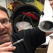
What follows is a step-by-step instructional guide for how to customize and use the new design, which involves using a small syringe that is attached to the flapper valve via a mono-filament line (50 lb test fishing line).
First thing to do is to watch this 3 minute video that explains how it works so you can get a visual of what needs to be done:
* don’t forget to Subscribe to my YouTube Channel for more updates, including a future instructional video that follows the steps below.
1) Determine Syringe Location
Decide where you want the syringe in order to determine how much tubing you will need.
For this remote-control scenario, you may need to mock up the drain pipes, but not necessarily. What you need to determine is the distance between the operating water level of the sump (where the primary drain line is located) and the position where you want the remote syringe – then, cut the hose to that length and proceed to the next step.
2) Setting up the syringe
Cut the line between the syringe and the flap and remove the line from both pieces.
Remove the plunger from the syringe body. Thread one end of the fishing line through the black sleeve on the plunger (between the sheathing and the plunger shaft).
Next, there is a little hole in the syringe plunger shaft, near the top (flat circle). Thread the fishing line through that hole so that it sticks out a few inches.
The next step involves creating a “ball” on the end of that line by touch the end of the line with flame from a lighter. Before you do this, it’s important to cover a couple basic safety items, especially if you have never burned plastic with flame before.
A) Melted plastic will stick to anything it gets on and will continue to remain melted (and hot) for several seconds. Do not allow melted plastic to drip onto your skin or clothes, but if it does, don’t wipe it up with you hand as it will stick to your hand. Now granted, we are talking about a very tiny amount of plastic, but it can still burn you.
B) Touch the end of the line with flame only briefly (far less than a half a second) to the end of the line that you just pushed through so that it starts to turn into a little “ball”. Immediately after flame contact is removed, blow on the “ball” to ensure that it is not on fire, then continue to blow on it, and do not touch the melted plastic at all for at least 30 seconds after flame contact.
C) You can repeat this process until the “ball” is about the size of a small pinhead so that the line cannot be pulled through the hole in the syringe shaft.
D) Avoid making flame contact for a long enough period to cause the line to start bubbling and crackling (i.e. it is on fire), and if you do, blow it out immediately and watch for any dripping.
E) don’t let this freak you out. Practice a few times if you need to, I have provided additional line in case you mess up 5 or more times…
So with all that taken into consideration, create the ball on the end of the line, then pull the other end of the line to remove the slack and pull the “ball” against the hole in the plunger shaft.
3) Re-assemble the syringe
Take your cut piece of vinyl tubing and push one end of it up on to the syringe body until it goes up over the tip and on to the main body of the syringe, just enough so that it stays in place (maybe 1/8″)
Feed the fishing line through the syringe and attached tubing, and take up most of the slack. Slide the black piece of sheathing on the syringe shaft to the top of the plunger, then push the plunger back into the syringe, keeping the line tight as you do it.
4) Assemble the drain
This is a bit easier to do before you have installed the scrubber drain, but you can prep the drain pipe ahead of time if you want. Preparation is really only needed if you have to control the drain remotely.
Cut the primary drain pipe so that when installed, the bottom of the pipe is between 1/2″ and 1″ under the surface of the water.
The valve is in the bubble blocker (the 2″ coupler with thumbscrews). With the thumbscrews on top, slide the bubble blocker on to the end of the drain pipe and tighten down the 3 screws until all are snug.
Feed the fishing line down between the blocker and the pipe near the location of the tip of the flapper, and feed the line through the tiny hole on the tip of the flapper.
5) Trimming the line and adding a second “ball”
Push the open end of the tubing that is attached to the end of the syringe into the gap between the bubble blocker and the pipe so that it is snug. Do this right above where the flap/hole is. You should only need to push it in about 1/2″.
If it’s not already, push the syringe plunger all the way in.
Hold the assembly vertical, and let the flap hang in lowest position (you may have to jiggle it and pull it down)
Make sure that you have removed all the slack in the fishing line, then make a “kink” or a mark on the line at a point about 1/4″ past where the line has passed through the hole in the flap.
Next, invert the assembly and let the flap sit closed.
Cut the line at the kink or mark point
Burn a ball on to that end (see process ans safety precautions above)
That’s it! You are done! Pull up on plunger to close valve, push the plunger to open the valve. It will not operate that great out of the water, but with flow pushing against the valve flapper, it will operate smoothly.
Once you have installed the scrubber and water is flowing, pull the syringe out in order to close the valve to the point where the drain stops gurgling and/or flushing, and you have reduced bubbles to a minimum (you will not be able to completely eliminate them initially – that is what the filter sock is for).
Once you have determined the best position for the syringe, slide the black sheathing that is around the plunger shaft down until it hits the syringe body. This locks the syringe in place.